
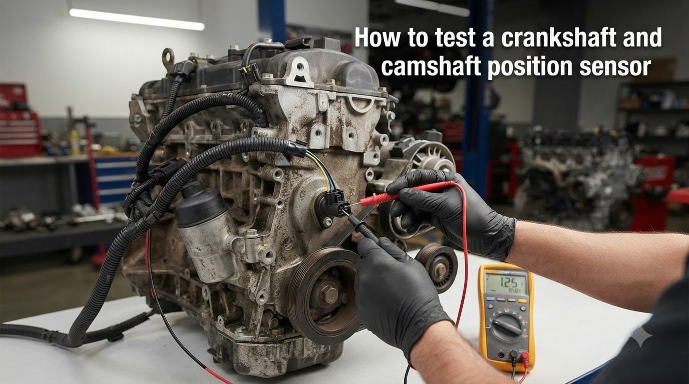
Learning how to test a crankshaft and camshaft position sensor saves you hundreds in shop labor and gets your engine back on the road faster. These two sensors are the unsung heroes of modern engine management. When one fails, your vehicle can refuse to start, stall at idle, or trigger a check engine light that sends you guessing at expensive parts.
I’ve spent weekends with a multimeter and a scan tool in my garage working through no-start conditions on three cars, and I’ll walk you through exactly what works. In this guide, I’ll show you how to tell whether the crank or cam sensor is the real culprit, what tools you actually need, and the step-by-step tests that produce a definitive answer. No guesswork, no throwing parts at the problem.
Table of Contents
What These Sensors Do and Why They Matter?
Your engine’s computer needs two critical pieces of information to keep things running: where the crankshaft is in its rotation, and where the camshaft is in its cycle. The sensors that report this data work together but measure different things.
The Crankshaft Position Sensor (CKP)
The crank sensor measures engine RPM and piston position. It usually sits near the crankshaft pulley, the flywheel, or the timing cover. Each time a tooth on the reluctor ring passes the sensor, it sends a pulse to the ECU. Many engines run on the crank sensor alone, which is why a bad crank sensor can leave you completely stranded.
The Camshaft Position Sensor (CMP)
The cam sensor tracks valve timing. It tells the ECU whether the number-one cylinder is on its intake or exhaust stroke. On engines with variable valve timing, the cam sensor is also critical for fuel injection sequencing. Without a working cam sensor, the engine usually still starts but runs poorly, throws a code, and may not pass emissions.
Both sensors commonly use one of two designs: a 2-wire variable reluctance (magnetic) sensor that generates its own AC voltage, or a 3-wire Hall effect sensor that needs a reference voltage from the ECU and sends back a digital on-off signal.
Symptoms of a Bad Crankshaft or Camshaft Position Sensor
The tricky part is that sensor failures often look like other problems. Here’s the symptom pattern I’ve learned to trust after years of chasing these issues.
Typical Symptoms of a Bad Crankshaft Sensor
Engine cranks but won’t start, or stalls immediately after starting
Sudden stalling while driving with no warning
Intermittent check engine light that comes and goes
Tachometer drops to zero while engine is running
No spark or no fuel pump activity on engines controlled by CKP
Engine dies when it gets hot, then restarts after cooling
Poor fuel economy combined with rough idle
A failing crank sensor often does not set a trouble code at all, which is what makes it so frustrating. The engine just stops dead, and you sit on the shoulder wondering what happened.
Typical Symptoms of a Bad Camshaft Sensor
Persistent check engine light with a P0340 or P0017 family code
Rough idle, especially when cold
Engine runs but loses power, especially under acceleration
Reduced fuel economy
Failed emissions test
Engine may start in “limp mode” with limited RPM
Cam sensor failures usually announce themselves with a code. If you see a P0340, P0341, P0345, or P0017, the cam sensor circuit is the first place to look.
Tools You Need to Test These Sensors
You don’t need a $4,000 scan tool to get reliable answers. For most DIY testing, three tools cover 90% of cases.
Digital multimeter that reads AC volts, DC volts, and resistance (ohms). A $30 meter works fine for sensors.
OBD-II scan tool that can read live data and crank the engine. Borrow one from AutoZone or buy a basic Bluetooth adapter for under $30.
Wiring diagram for your specific vehicle. AllDataDIY, Mitchell1, or even a free forum search for your make and model will get you there.
For advanced diagnostics, a lab scope or oscilloscope is the gold standard. I’ll cover that method at the end, but it’s optional for most home mechanics.
Safety Precautions Before You Start
Working around a cranking engine is genuinely dangerous. I’ve watched a friend’s wedding ring catch on a spinning pulley, and I never forget it. Before you begin:
Disconnect the negative battery terminal if you will be unplugging sensors or working with the ignition off.
Keep loose clothing, hair, jewelry, and lanyards away from belts, pulleys, and the fan.
Make sure the transmission is in Park (automatic) or Neutral (manual) with the parking brake set.
Never touch a sensor or wire with the engine running unless you are specifically testing live voltage.
Use insulated multimeter probes and check them for cracks before each use.
If you are not comfortable with these steps, stop and take the vehicle to a professional. The cost of a tow is far less than a hand injury.
How to Identify Your Sensor Type: 2-Wire vs 3-Wire
Before you test anything, look at the connector. The number of wires tells you how to test it.
A 2-wire sensor is a magnetic variable reluctance type. It generates its own AC voltage when a reluctor ring spins past it. The two wires are signal and signal-ground, both connected to the ECU.
A 3-wire sensor is a Hall effect or active sensor. It needs a 5-volt reference from the ECU, a ground, and sends back a signal wire. You’ll see three distinct terminals on the plug.
If your wiring diagram lists a 4-wire sensor, you’re looking at a sensor with a separate shielded ground. Test it like a 3-wire but check the shield for continuity to chassis ground.
How to Test a 2-Wire Crankshaft or Camshaft Sensor
Two-wire sensors are the easiest to diagnose. You have two tests: a static resistance check and a dynamic AC voltage check while the engine cranks.
Step 1: Resistance test (sensor at room temperature). Unplug the sensor connector. Set your multimeter to ohms. Touch the two probes to the two sensor terminals.
A good sensor typically reads between 200 and 1,200 ohms. Check your service manual for the exact spec.
Open circuit (OL on the meter) means the internal coil is broken. Replace the sensor.
Very low resistance, like under 100 ohms, suggests a short. Replace the sensor.
Step 2: AC voltage test while cranking. Reconnect the sensor. Set your multimeter to AC volts (the 2V scale works well). Back-probe the signal wires at the harness or use piercing probes if needed.
Have a helper crank the engine for 5 seconds while you watch the meter.
A healthy 2-wire sensor produces at least 0.5 to 1.0 volts AC while cranking. Many produce 2 to 5 volts.
Zero voltage or a very weak signal with good resistance means the magnet is weak or the reluctor ring is damaged. Replace the sensor.
One important detail: a 2-wire sensor will only produce AC voltage when the reluctor ring is spinning. If you test the wires with the engine off, you’ll see 0 volts and that’s normal.
How to Test a 3-Wire Hall Effect Crankshaft or Camshaft Sensor
Three-wire sensors need the ECU powered up to work, so you test them with the key on and the engine off (or cranking). You have three measurements to verify.
Step 1: Reference voltage. With the key on and engine off, back-probe the power wire. You should see roughly 5 volts (some Chevys use 12 volts, so check your spec sheet). No voltage means a wiring or ECU problem, not a bad sensor.
Step 2: Ground. Switch the multimeter to continuity. Touch one probe to the ground terminal at the sensor and the other to a known chassis ground. You should hear a beep or see 0 ohms. If ground is open, fix the wiring before condemning the sensor.
Step 3: Signal wire. With the multimeter on DC volts, back-probe the signal wire. Have a helper crank the engine. A working sensor will swing between roughly 0 and 5 volts (or 0 and 12, depending on system) as the reluctor passes by. A steady 0V or steady 5V with no pulsing means the sensor is bad.
In my experience, a 3-wire sensor that has the right reference voltage and a clean ground almost always tests bad at the signal wire. The internal Hall element is the weak link.
Testing Without a Multimeter: Scan Tool and Code Reading
If you don’t have a multimeter handy, a scan tool still gives you useful data. Plug into the OBD-II port and watch the live RPM reading while cranking the engine.
A working crank sensor will show RPM on the scan tool, usually 100 to 300 RPM during cranking.
Zero RPM during cranking on a no-start engine strongly suggests a crank sensor or wiring fault.
Pay attention to the trouble codes as well. The common codes you’ll see related to these sensors are:
P0335 – Crankshaft position sensor circuit malfunction
P0336 – CKP sensor range or performance problem
P0337 – CKP sensor low input
P0338 – CKP sensor high input
P0340 – Camshaft position sensor circuit malfunction
P0341 – CMP sensor range or performance problem
P0017 – Crankshaft/camshaft position correlation
But remember the forum wisdom: a code does not always mean a bad sensor. Wiring, connectors, and even the reluctor ring can set the same code. Always confirm with a multimeter before replacing.
Advanced: Oscilloscope and Bench Testing
An oscilloscope (or lab scope) shows you the actual waveform your sensor is producing. This is the only way to catch a sensor that passes all multimeter tests but fails under real engine vibration. A scope is also the only way to know if the reluctor ring has a missing tooth.
Connect the scope to the signal wire and crank the engine. A healthy Hall effect sensor produces a square wave that toggles cleanly between 0 and reference voltage. A healthy variable reluctance sensor produces a sine wave. Look for:
Consistent amplitude across all pulses
Clean rising and falling edges with no ringing or noise
Correct number of pulses for the reluctor design (a 60-2 wheel produces 58 pulses plus one missing tooth every revolution)
For a bench test, remove the sensor and attach it to a variable speed drill or a 12V motor with a trigger wheel. Spin it and watch the output. If you can spin it to about 1,000 RPM equivalent and the voltage is clean and similar to a known-good sensor, it’s probably fine. This is the fastest way to confirm a sensor you suspect is intermittent.
Sensor or Wiring Harness: How to Tell
This is the most common diagnostic mistake I see. A new sensor doesn’t fix the problem because the actual fault is in the harness. Use this quick decision tree before swapping parts.
Sensor voltage at the ECU is good, but the sensor still tests bad at the connector: Replace the sensor.
Sensor voltage at the connector is good, but the ECU sees no signal: Bad wiring or connector. Inspect for chafed insulation, corroded pins, and water ingress.
Reference voltage is missing at the sensor: Check the ECU-side wiring, then the ECU itself. Don’t replace the sensor.
Sensor tests good, but the code keeps coming back: Inspect the reluctor ring for damage, misalignment, or debris. A cracked tone wheel acts exactly like a bad sensor.
A wiggle test is also useful. With the engine idling, gently wiggle the sensor harness and connectors. If the engine stumbles or cuts out as you wiggle, you have a broken wire inside the insulation. Replace the harness pigtail rather than the sensor.
Frequently Asked Questions
How do I know if my crankshaft or camshaft sensor is bad?
A bad crank sensor usually causes a no-start or sudden stalling condition, often without a code. A bad cam sensor usually triggers a check engine light with codes like P0340 or P0017, accompanied by rough idle and reduced power. Scan for codes first, then confirm with a multimeter test of the sensor itself.
Can a crankshaft position sensor be tested with a multimeter?
Yes. Test a 2-wire sensor for resistance (typically 200 to 1,200 ohms) and for AC voltage output while cranking (at least 0.5V). Test a 3-wire sensor for 5V reference voltage, clean ground, and a pulsing DC signal on the signal wire while cranking. Any reading outside spec points to a bad sensor or wiring problem.
What are the 7 symptoms of a bad crankshaft position sensor?
The most common symptoms are: (1) engine cranks but won’t start, (2) sudden stalling while driving, (3) intermittent check engine light, (4) tachometer drops to zero, (5) no spark or fuel pump activation, (6) engine dies when hot then restarts when cool, and (7) rough idle with poor fuel economy.
Can a crankshaft sensor fail without throwing a code?
Yes, this is one of the most frustrating realities of crank sensor diagnosis. A failing crank sensor may produce a weak or intermittent signal that the ECU never flags as a fault, but the engine still stalls. In these cases, an oscilloscope or bench test is the only way to confirm the failure.
Can I test a camshaft position sensor with a multimeter?
Yes. Test a 2-wire cam sensor with resistance and AC voltage cranking tests, just like a crank sensor. Test a 3-wire cam sensor by checking for reference voltage, ground, and a switching DC signal on the signal wire. Compare readings to the spec sheet for your specific engine.
How do I tell if the problem is the sensor or the wiring?
Test the sensor at the connector first. If the sensor tests good at the connector but the ECU still sees no signal, the wiring harness is the problem. Check for reference voltage at the sensor, then back-probe the signal wire at the ECU. A missing reference voltage almost always points to wiring or ECU, not the sensor itself.
Wrapping Up: How to Test a Crankshaft and Camshaft Position Sensor With Confidence
You’ve now got a complete method for how to test a crankshaft and camshaft position sensor using tools most home mechanics already own. Start by identifying whether you have a 2-wire or 3-wire design, run the right multimeter tests, confirm with a scan tool when possible, and use an oscilloscope for the trickiest intermittent problems. Above all, verify the wiring before swapping parts.
Grab your multimeter, pull up your vehicle’s wiring diagram, and run the tests in order. If your readings match the spec, you’ve saved yourself a wasted part. If they don’t, you’ll know exactly which sensor to replace and why. That’s the kind of diagnosis that turns a frustrating problem into a Saturday afternoon fix.