
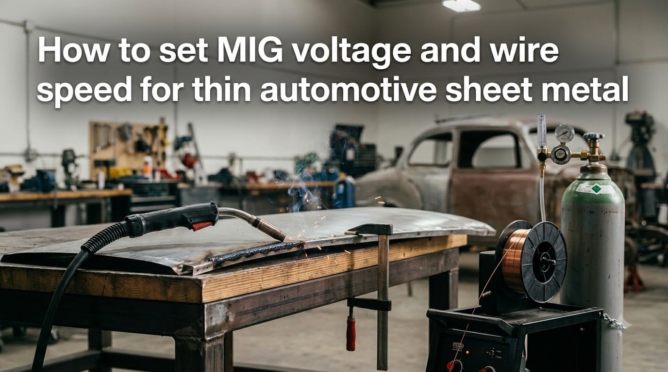
Learning how to set MIG voltage and wire speed for thin automotive sheet metal is the single biggest challenge DIY restorers and body shop techs face. You get one shot at welding a patch panel before burn-through turns it into scrap. I have spent years welding car body panels, and the settings that work on thick steel will destroy thin sheet in seconds.
The good news is that thin metal welding comes down to a handful of predictable numbers. Once you understand the relationship between voltage, wire feed speed, wire diameter, and material thickness, you can dial in your machine for any gauge on a car. This guide walks through every setting you need, from wire selection to stitch welding technique, with a quick-reference chart no competitor offers.
Table of Contents
What Counts as Thin Automotive Sheet Metal?
Thin automotive sheet metal refers to steel between 24 gauge (0.024 inch / 0.6mm) and 18 gauge (0.048 inch / 1.2mm) in thickness. The American Welding Society classifies any material 3/16 inch or thinner as “thin material” under AWS D1.3, but automotive body panels sit at the extreme thin end of that range.
Most car bodies use 20 gauge (0.036 inch) for exterior panels, 22 gauge (0.030 inch) for inner structures, and 24 gauge (0.024 inch) for lightweight panels on modern vehicles. Classic cars and trucks often use slightly thicker 18 gauge steel on structural panels like rockers and floorboards.
At these thicknesses, heat input is your biggest enemy. The metal absorbs heat faster than it can dissipate, which means one second too long on the trigger and you have a hole. Every setting recommendation in this guide exists to manage that heat.
Choose the Right Wire Diameter First
Wire diameter is the foundation of your settings. You cannot compensate for oversized wire by adjusting voltage and wire speed alone. For thin automotive sheet metal, smaller wire is always better because it requires less amperage to melt and gives you finer control over the weld pool.
Here is how I match wire to material thickness:
0.023 inch (0.6mm) wire — Best for 22 to 24 gauge automotive steel. This is my go-to for exterior body panels, firewalls, and anything under 0.030 inch thick. It runs at the lowest amperage and produces the smallest weld pool.
0.030 inch (0.8mm) wire — Best for 18 to 20 gauge steel. Good all-around choice for floor pans, rocker panels, and patch panels on classic cars. Slightly faster deposition than 0.023.
0.035 inch (0.9mm) wire — Use only on 18 gauge or thicker structural panels. Too aggressive for exterior sheet metal and will burn through if you are not extremely careful.
Always use solid mild steel wire with shielding gas for thin automotive work. Flux-core wire penetrates deeper and runs hotter, making it a poor choice for sheet metal under 20 gauge. Forum users across r/Welding and mig-welding.co.uk consistently recommend switching to solid wire for anything below 0.8mm thickness.
ER70S-6 is the standard wire classification for automotive mild steel. It handles the mill scale and light contamination typical of car panels better than general-purpose wire.
How to Set MIG Voltage and Wire Speed for Thin Automotive Sheet Metal
Setting MIG voltage and wire speed for thin automotive sheet metal requires matching three variables: wire diameter, voltage, and wire feed speed (which controls amperage). The process follows a logical order that gives you repeatable results every time.
Here is the step-by-step procedure I use on every panel:
Step 1: Determine material thickness. Use a gauge wheel or caliper to measure the steel. Convert to thousandths of an inch (18 gauge = 0.048, 20 gauge = 0.036, 22 gauge = 0.030, 24 gauge = 0.024).
Step 2: Select wire diameter based on thickness. Use 0.023 inch wire for 22 to 24 gauge, 0.030 inch for 18 to 20 gauge. Refer to the wire selection section above.
Step 3: Calculate target amperage. Use the rule of 1 amp per 0.001 inch of material thickness. For 20 gauge (0.036 inch), that gives you approximately 36 amps. For 24 gauge (0.024 inch), target around 24 amps.
Step 4: Set voltage based on wire size and amperage. Start in the 14 to 16 volt range for 0.023 wire at 20 to 40 amps. For 0.030 wire at 40 to 60 amps, start at 15 to 17 volts. Lower voltage gives you a tighter, more controllable arc.
Step 5: Set wire feed speed. Wire feed speed directly controls amperage. Use the IPM multipliers in the next section to calculate your starting speed, then fine-tune by listening to the arc.
Step 6: Test on scrap of the same thickness. Never test on the actual panel. Use a cutoff of the same gauge and adjust from there. A proper arc sounds like frying bacon — a crisp, steady crackle.
Step 7: Fine-tune voltage up or down in 0.5 volt increments. If the wire stubs into the metal, increase voltage. If the arc is loud and spattery with excessive spatter, decrease voltage by half a volt.
Quick Reference Settings Chart by Metal Thickness
This chart combines all the settings I use for common automotive sheet metal gauges. These are starting points — always test on scrap and fine-tune for your specific machine, gas flow, and joint configuration.
| Gauge | Thickness | Wire Diameter | Voltage Range | Wire Feed Speed (IPM) | Approx. Amperage |
|---|---|---|---|---|---|
| 24 ga | 0.024 inch (0.6mm) | 0.023 inch | 12 to 14 V | 100 to 150 IPM | 20 to 30 amps |
| 22 ga | 0.030 inch (0.8mm) | 0.023 inch | 13 to 15 V | 130 to 180 IPM | 25 to 35 amps |
| 20 ga | 0.036 inch (0.9mm) | 0.023 to 0.030 inch | 14 to 16 V | 150 to 200 IPM | 30 to 45 amps |
| 18 ga | 0.048 inch (1.2mm) | 0.030 inch | 15 to 17 V | 180 to 250 IPM | 40 to 60 amps |
No competitor publishes a chart this specific for automotive applications. Print it and tape it to your welder. The voltage ranges assume short circuit transfer mode with 75/25 argon/CO2 gas.
Wire Feed Speed and Amperage Rules
Wire feed speed controls amperage, and amperage controls heat input. This is the most important relationship to understand for thin metal welding. Slower wire speed means less wire entering the arc, which means lower amperage and less heat. Faster wire speed means more wire, more amperage, and more heat.
For thin material, you generally want slower wire speed than what you would run on thick plate. This keeps heat input low and gives you more time to react before burn-through occurs.
MillerWelds publishes IPM multipliers that I use as a starting formula:
0.023 inch wire: Multiply target amps by 3.5 to get IPM. Example: 30 amps x 3.5 = 105 IPM.
0.030 inch wire: Multiply target amps by 2.0 to get IPM. Example: 50 amps x 2.0 = 100 IPM.
0.035 inch wire: Multiply target amps by 1.6 to get IPM. Example: 60 amps x 1.6 = 96 IPM.
These multipliers get you in the ballpark. From there, listen to the arc and watch the weld pool. If the wire is pushing back against the gun (stubbing), increase wire speed. If you are getting excessive spatter and a violent arc, decrease wire speed slightly.
Shielding Gas and Stickout Setup
Use a 75/25 mix of argon and CO2 (commonly called C25) for all thin automotive sheet metal work. Pure CO2 penetrates too aggressively and produces excessive spatter on thin material. Straight argon will not work for steel at all. The 75/25 blend gives you a stable short circuit transfer arc with minimal spatter and controllable penetration.
Set your gas flow rate to 20 to 25 cubic feet per hour (CFH). Too low and you get porosity from inadequate shielding. Too high and you create turbulence that pulls atmospheric air into the weld zone, which also causes porosity.
Stickout — the distance from the contact tip to the work piece — should be kept between 1/4 inch and 5/8 inch maximum. For thin metal, I keep it tight at around 1/4 to 3/8 inch. Shorter stickout concentrates the arc and keeps voltage consistent, which is critical when you are running at low voltage settings where small changes have a big impact.
Short circuit transfer mode is what makes MIG welding thin sheet metal possible. In this mode, the wire literally touches the work piece and short-circuits, depositing a small droplet of metal before pulling back. This happens 20 to 200 times per second, creating a series of small, controlled deposits rather than a continuous spray of metal. It produces the lowest heat input of any MIG transfer mode.
Make sure your machine is set to DCEP (direct current electrode positive), also called reverse polarity. This concentrates heat at the wire tip rather than the work piece, which helps limit how much heat goes into your panel.
How to Prevent Burn-Through on Car Panels?
Burn-through is the number one complaint I hear from people welding automotive sheet metal. It happens when heat input exceeds what the thin metal can handle, causing the weld pool to fall through and create a hole. Prevention comes down to four strategies working together.
Strategy 1: Reduce heat at the source. Use the thinnest wire practical, the lowest voltage that still gives a stable arc, and the slowest wire speed that maintains deposition. Every setting should be biased toward less heat.
Strategy 2: Use a backing bar. Place a piece of thick copper or brass behind the weld joint. These metals conduct heat away from the panel rapidly and will not fuse to steel. This is one of the most effective tricks from the fabrication community. A copper backing bar can absorb enough heat to prevent burn-through even on 24 gauge steel.
Strategy 3: Weld in short bursts. Never lay a continuous bead on thin metal. Use stitch welding or tack-and-skip technique to let the metal cool between deposits. I cover the exact technique in the next section.
Strategy 4: Clean the panel thoroughly. Automotive panels often have coatings, paint, galvanizing, or underbody sealer that contaminates the weld and changes heat absorption. Grind to bare metal at least 1 inch on each side of the weld seam. Contaminated metal requires more heat to weld, which pushes you closer to burn-through.
Forum welders also recommend using a brass or copper spoon behind holes if one develops. You can fill small holes by building up around the edges while the backing absorbs excess heat.
Stitch Welding Technique for Automotive Panels
Stitch welding is a non-continuous welding process where you make short weld segments with cooling time between each one. It is the standard technique for car body panels because it limits total heat input and prevents warping. MIG-Welding.co.uk describes it as the essential thin metal technique, and I agree completely.
Here is the stitch welding process I follow for patch panels and body repair:
Step 1: Tack weld the full seam. Place tacks every 1 to 2 inches along the entire joint. This holds the panel in position and prevents expansion from pulling it out of alignment. Start tacking from the center and work outward in alternating directions to distribute heat evenly.
Step 2: Connect the tacks in short segments. Weld a segment of 1/2 to 1 inch between two tacks, then stop. Do not weld the adjacent segment next. Move to a different area of the seam and weld there. This is called skip welding or back-step welding.
Step 3: Let each segment cool. Wait 5 to 10 seconds between welds. The panel should be warm but not hot to the touch. If you cannot hold your hand near the weld zone, you are welding too fast without enough cooling time.
Step 4: Work the entire seam progressively. Fill in the gaps between tacks in a random or alternating pattern. Never weld two segments back-to-back. The goal is to distribute heat across the whole panel rather than concentrating it in one area.
Step 5: Grind flush if needed. For exterior body panels, grind the weld flush with a flap disc. If you see pinholes or undercut, go back and fill them with a quick tack rather than trying to weld over the entire seam again.
This technique takes patience. A patch panel that takes 2 minutes of actual arc time might take 20 minutes of wall-clock time because of the cooling periods. But this is what separates a panel that fits properly from one that warps and needs to be cut out and redone.
Troubleshooting Common MIG Weld Problems on Thin Metal
Reading your weld bead tells you exactly what to adjust. MillerWelds has an excellent bead evaluation guide, and here is my automotive-focused version for thin sheet metal:
Wire stubbing into the metal (no fusion): Voltage is too low or wire speed is too high. Increase voltage by 0.5 volts or decrease wire feed speed by 10 to 20 IPM.
Loud, violent arc with excessive spatter: Voltage is too high. Decrease voltage by 0.5 to 1 volt. Also check that your stickout is not too long.
Weld sits on top of the metal (cold lap): Wire speed is too high relative to voltage, or travel speed is too fast. Reduce wire feed speed or slow your travel speed.
Excessive penetration or burn-through: Everything is too hot. Reduce voltage, reduce wire speed, switch to thinner wire, or increase travel speed. Also check that you are using short circuit transfer mode rather than globular.
Porosity (small holes in the weld): Gas shielding is inadequate. Check for drafts in your work area, increase gas flow to 25 CFH, clean the nozzle of spatter buildup, verify your gas is 75/25 argon/CO2, and ensure the panel is clean to bare metal.
Undercut along the bead edges: Voltage too high or travel speed too slow. Lower voltage slightly or move faster along the joint.
Automotive Panel Repair Tips
Automotive panel welding has specific challenges that general sheet metal guides do not address. Here are the techniques that come from actual car restoration experience rather than textbook theory.
Patch panel alignment: Overlap your patch panel by 1/4 inch and use a flange tool to create a slight offset. This gives the weld a place to sit flush after grinding. Butt joints work but require precise gap control — aim for a consistent 1/16 inch gap along the entire seam.
Firewall repair: Firewalls are often 20 or 22 gauge and sit above heat-sensitive components. Remove all wiring, insulation, and rubber grommets within 12 inches of the weld zone. Use a heat-resistant blanket to protect anything you cannot remove. The backside of a firewall is impossible to reach with a backing bar, so keep your weld segments extra short.
Rocker panels: These are structural and often thicker (18 gauge on many vehicles). But they have inner and outer skins that can warp independently. Tack the inner and outer skins separately and weld each layer with its own stitch sequence.
Floor pans: Floor pans are forgiving because they are flat and relatively thick. Use 0.030 inch wire for 18 to 20 gauge floors. Spot weld plugs of 5/16 inch every 2 inches for factory-style appearance, or stitch weld for maximum strength.
Panel gap management: As you weld, the panel will expand and gaps will close. Start with slightly larger gaps than you think you need — about 1/16 to 3/32 inch. If gaps close completely during welding, stop and re-cut the seam with a cutoff wheel before continuing.
Duty cycle awareness: Thin metal welding is inherently intermittent, which actually works in your favor. Most 140 to 180 amp MIG welders have a duty cycle of 20 to 30 percent at rated output. Since you are welding in short bursts with cooling time, you will rarely hit the duty cycle limit. But if your machine has a thermal overload indicator, respect it and let the machine cool.
FAQs
What are the best MIG welding settings for thin metal?
For thin automotive sheet metal (18 to 24 gauge), use 0.023 inch wire, 12 to 17 volts, and 100 to 200 IPM wire feed speed with 75/25 argon/CO2 shielding gas. Target approximately 1 amp per 0.001 inch of material thickness. Always weld in short stitch segments with cooling time between passes.
Do I want slower or faster wire speed for welding thin material?
You want slower wire speed for thin material. Lower wire feed speed reduces amperage and heat input, which prevents burn-through. For 24 gauge steel, start around 100 to 130 IPM. Increase only if the wire stubs into the metal without fusing properly.
What are the best MIG welding settings for car bodywork?
For car body panels, use 0.023 inch wire for 20 to 24 gauge steel at 14 to 16 volts and 130 to 200 IPM. Use 75/25 argon/CO2 gas at 20 to 25 CFH. Set stickout to 1/4 to 3/8 inch and weld in 1/2 to 1 inch stitches with 5 to 10 second cooling intervals.
How to set MIG wire feed speed?
Calculate target amperage at 1 amp per 0.001 inch of thickness, then multiply by the wire size factor: 3.5 for 0.023 inch wire, 2.0 for 0.030 inch wire, or 1.6 for 0.035 inch wire. Test on scrap, listen for a steady crackle like frying bacon, and fine-tune in 10 IPM increments.
Conclusion
Setting MIG voltage and wire speed for thin automotive sheet metal comes down to four principles: use the smallest wire practical, keep voltage low, slow your wire feed speed to match the amperage rule, and always weld in short stitches with cooling time between passes. The quick-reference chart in this guide gives you exact starting numbers for every common automotive gauge.
Print that chart, tape it to your welder, and always test on scrap before touching the actual panel. With these settings and the stitch welding technique, you can tackle any body panel repair without burn-through or warping. Take your time, let the metal cool, and your welds will look professional on the first try.