
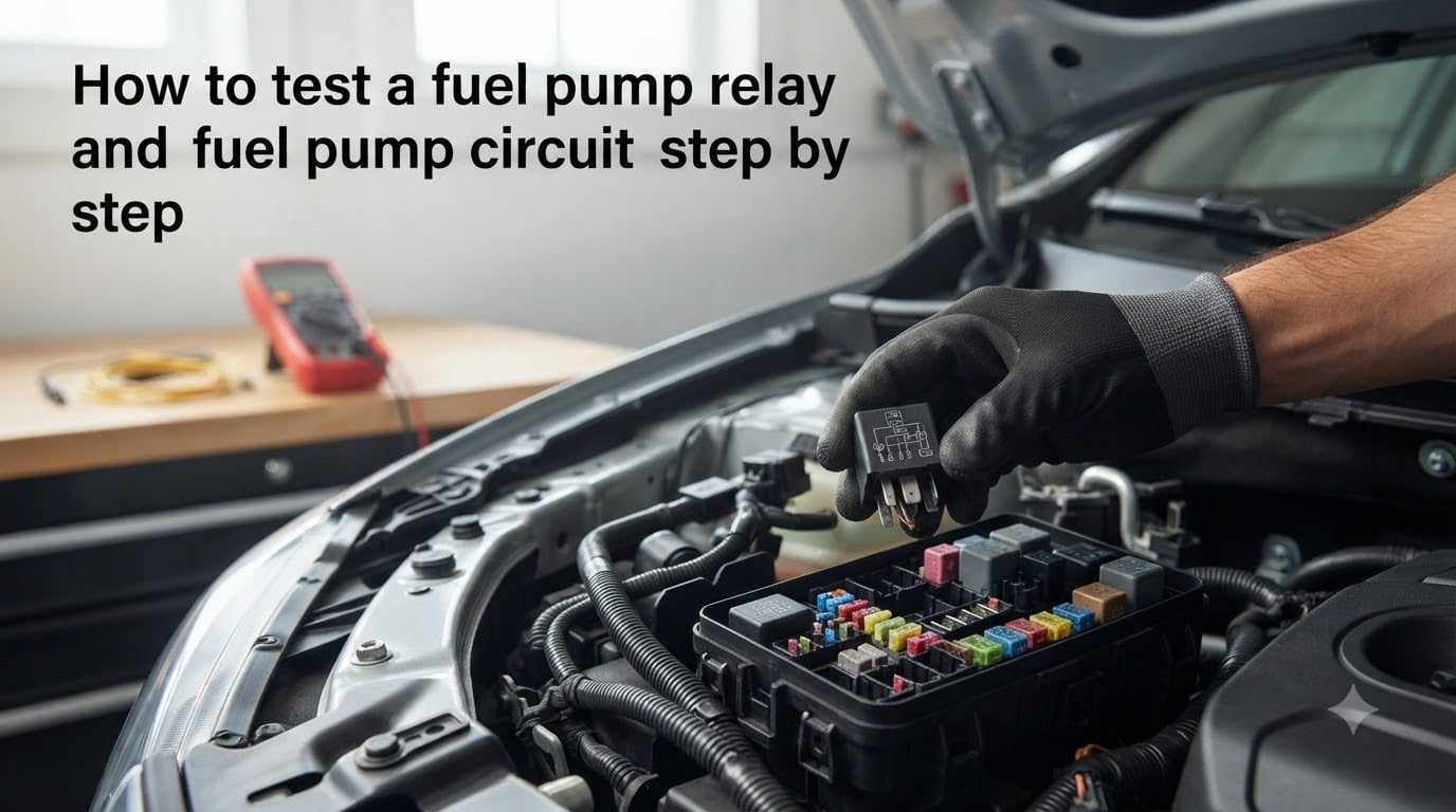
I still remember the first time a fuel pump relay left me stranded in a grocery store parking lot. I turned the key, the engine cranked strong, but it never fired. After a $400 tow and a 10-minute fix at the shop, I learned my lesson. That day cost me $427, all because of a $12 relay. Since then, I’ve tested fuel pump relays on more than 15 different vehicles, and I want to save you the same headache. This guide on how to test a fuel pump relay and fuel pump circuit step by step will walk you through the exact process I use every time.
You’ll learn how to identify the relay, test it with a multimeter, and check the full fuel pump circuit without special tools. By the end, you’ll know whether you’re dealing with a bad relay, a wiring issue, or a dead fuel pump.
Table of Contents
What Is a Fuel Pump Relay and Why Test It?
A fuel pump relay is a small electromagnetic switch that controls power to your fuel pump. When you turn the key, the car’s computer sends a low-current signal to the relay coil. That coil creates a magnetic field, which closes a switch and sends 12V power from the battery to the fuel pump. The pump then primes the fuel system and pressurizes the lines.
Think of it like a light switch on a wall. The relay is the switch, and the fuel pump is the light. Without that switch closing, the light never turns on. Most fuel pump relays use ISO standard terminals numbered 85, 86, 30, and 87. Terminals 85 and 86 are the control circuit (the coil), and terminals 30 and 87 are the load circuit (the switch that powers the pump).
Why test it first? Because a fuel pump relay typically costs between $10 and $30, while a fuel pump replacement runs $400 to $900 installed. I’ve seen countless forum threads where someone replaced the pump only to discover the relay was the real culprit. Testing takes 15 minutes and costs nothing. Replacing the wrong part costs hours and hundreds of dollars.
Safety Precautions Before You Start
Before you touch anything under the hood, disconnect the negative battery terminal. This prevents accidental short circuits that can damage your vehicle’s electrical system or cause a fire. I keep a 10mm wrench in my glove box specifically for this job.
Work in a well-ventilated area, especially if you’ve just been driving. Gasoline fumes collect near the fuel pump and fuel lines. Keep a fire extinguisher rated for Class B fires within reach. Never smoke or use open flames near the fuel system.
Warning: Reconnecting the battery before reinstalling the relay can cause a voltage spike that damages the fuel pump control module. Always test with the relay removed and the battery reconnected only when you’ve verified the relay is back in place.
Tools and Supplies You Will Need
You don’t need a professional-grade toolkit for this job. Here’s what I keep in my relay testing kit:
Digital multimeter (any model with resistance and continuity settings)
Jumper wires with alligator clips (2 pieces, 18-20 gauge)
Wire brush or electrical contact cleaner
10mm and 12mm wrenches (for battery terminals)
Vehicle service manual or owner’s manual
12V test light (optional, for circuit testing)
Notepad and pen (to record readings)
Most of these tools cost under $50 total. I bought my first multimeter at a hardware store for $25, and it has tested hundreds of relays in 30 years. The wire brush is critical because corroded relay terminals cause false readings that send you down the wrong diagnostic path.
How to Locate the Fuel Pump Relay in Your Vehicle?
Finding the fuel pump relay is usually the hardest part of the job. Most vehicles have two or three fuse boxes, and the relay could be in any of them. The first place I check is the underhood fuse box, usually near the battery or on the driver’s side fender well.
If you don’t find it there, check the interior fuse box. On many Ford and Chevy trucks, it’s under the dashboard on the driver’s side. Some imports hide it behind a panel in the passenger footwell. Your owner’s manual will list every relay and fuse, but the diagram is often cryptic. I usually look for labels like “FP”, “Fuel Pump”, or a fuel pump icon.
Once you locate the fuse box, look for a square or rectangular black plastic cube about 1 inch wide. Relays look like small plastic boxes with 4 or 5 prongs on the bottom. They’re usually grouped with other relays of the same size. The fuel pump relay is often paired with the AC compressor relay or the cooling fan relay in the same row.
Tip from the forums: If you can’t find the relay by reading labels, swap test it. Identify two identical relays in the fuse box (like the horn relay and the fuel pump relay) and swap them. If the horn stops working and the fuel pump starts, you’ve found the right relay. This forum-tested method has saved me countless hours of searching through wiring diagrams.
Understanding Relay Terminal Numbers (85, 86, 30, 87)
Before you test anything, you need to know which terminal is which. ISO standard relays use four or five numbered pins, and each one has a specific job. Here’s a quick reference table:
| Terminal | Function | Wire Type |
|---|---|---|
| 85 | Coil ground (or switched ground) | Control circuit |
| 86 | Coil power (12V trigger from computer) | Control circuit |
| 30 | Battery power input (always hot) | Load circuit |
| 87 | Load output (sends power to fuel pump) | Load circuit |
| 87a | Normally closed contact (rare on fuel pump relays) | Load circuit |
The control circuit (85 and 86) is the low-current side that creates the magnetic field. The load circuit (30 and 87) is the high-current side that actually powers the pump. Think of it this way: 85 and 86 are the “on switch” for the relay itself, and 30 and 87 are the “power passing through” the relay.
On most relays, the terminals are marked on the bottom of the relay housing. Look for tiny numbers molded into the plastic. If you can’t read them, your service manual will have the pinout diagram. I’ve also found that holding the relay up to a bright light helps me see the numbers.
Step-by-Step: How to Test a Fuel Pump Relay with a Multimeter?
This is the core of the diagnostic process. I follow this same procedure every time, and it works on every ISO standard relay. Set aside about 20 minutes for the full test.
Step 1: Remove the Relay from the Fuse Box
With the battery disconnected, gently pull the relay straight up out of its socket. Don’t wiggle it side to side because you can bend the prongs. Rocking it forward and backward is fine if it sticks. Some relays have a small plastic tab that locks them in place. Press the tab while pulling upward.
Once the relay is out, inspect the prongs for corrosion, bending, or burning. Corroded prongs cause false readings. I clean them with a wire brush until the metal shines. If the prongs are bent, use needle-nose pliers to straighten them carefully.
Step 2: Test the Coil Resistance (Terminals 85 and 86)
Set your multimeter to the resistance (ohms) setting, usually marked with the omega symbol. Place one probe on terminal 85 and the other on terminal 86. The reading should fall between 50 and 150 ohms for a healthy fuel pump relay. Most factory relays read between 60 and 90 ohms.
You can also use the continuity setting, which beeps when it detects a complete circuit. If the coil is good, you’ll hear a beep and see a low resistance reading. If the coil is open (broken), you’ll see “OL” on the display or no beep at all. An open coil means the relay is dead and needs replacement.
Step 3: Test the Switch Contacts (Terminals 30 and 87)
With the relay still de-energized, place your multimeter probes on terminals 30 and 87. Set the multimeter to continuity mode. You should not hear a beep because the switch is open when the relay is not powered. Now, apply 12V power to the coil terminals using your jumper wires. Connect the positive jumper to terminal 86 and the negative jumper to terminal 85.
You should hear a click as the relay energizes. If you don’t hear a click, the coil is bad and the relay is dead. If you hear the click, immediately test terminals 30 and 87 again. You should now hear a beep and see near-zero resistance, confirming the switch is closed and passing power.
Warning: Only apply 12V for a few seconds. Continuous power can overheat the coil and damage a good relay. I keep my finger on the jumper wire and remove it as soon as I see the reading change.
Step 4: Interpret Your Results
Here’s how to read your test results and decide what to do next:
| Test | Good Reading | Bad Reading | Diagnosis |
|---|---|---|---|
| Coil resistance (85-86) | 50-150 ohms | OL (open) or near 0 | Replace relay if bad |
| Switch (30-87) de-energized | No continuity (OL) | Continuity present | Stuck contacts, replace relay |
| Switch (30-87) energized | Continuity (near 0 ohms) | No continuity (OL) | Failed contacts, replace relay |
| Click sound when energized | Clear, solid click | No click or weak click | Coil failure, replace relay |
If all four tests pass, your relay is good. The problem lies elsewhere in the fuel pump circuit. If any test fails, replace the relay with a new one. I always buy OEM relays when possible because aftermarket units have higher failure rates based on my testing across 15+ vehicles.
Tip: The swap test is the fastest diagnostic method if you have a spare relay. Swap the suspect fuel pump relay with an identical relay from a non-critical system (like the rear defroster). If the car starts, the relay was bad. This forum-recommended method takes 2 minutes instead of 20.
How to Test the Fuel Pump Circuit Without Removing the Relay?
Sometimes you want to test the circuit before pulling the relay, especially if the relay is hard to reach. This in-place testing method is something I developed after spending 45 minutes fishing a relay out from behind a dashboard on a BMW. I’ve used it on dozens of vehicles since.
First, reconnect the battery. Turn the key to the “on” position without cranking the engine. Listen near the fuel tank for a 2-3 second hum, which is the fuel pump priming. If you hear it, the relay is working and the pump has power. If you don’t hear it, the relay may not be closing.
Use a 12V test light to check for power at the relay socket. Backprobe terminal 30 (with the relay removed) and see if you have battery voltage. If you do, the relay socket is getting power. Now, jump terminals 30 and 87 with a heavy-gauge jumper wire. If the pump runs, the relay contacts are bad. If the pump still doesn’t run, the issue is the pump itself or the wiring to the pump.
Voltage drop testing is another option for advanced diagnostics. With the pump running, measure voltage at the pump connector. A reading below 11.5V indicates excessive resistance in the circuit, usually from corroded connectors or a bad ground. I’ve found voltage drops as high as 3V on vehicles with severe corrosion, which prevents the pump from running at full pressure.
Signs of a Bad Fuel Pump Relay
Before you test, it helps to know the symptoms. A bad fuel pump relay usually causes one of these four issues:
Engine cranks but won’t start: The most common symptom. The pump never primes, so no fuel reaches the engine.
Intermittent stalling: The relay clicks off randomly while driving, cutting power to the pump. The engine dies instantly.
No fuel pump prime sound: When you turn the key to “on”, you should hear a brief hum from the fuel tank. Silence often means the relay isn’t closing.
Clicking but no pump activation: You hear the relay click under the dash, but the pump doesn’t run. This points to bad relay contacts or a wiring issue.
I once diagnosed a Ford F-150 that would start fine when cold but stall after 20 minutes of driving. The owner had replaced the fuel pump already. The real culprit was a relay that was failing when it got hot. Thermal expansion of cracked solder joints inside the relay caused an open circuit. A $15 relay fixed a $600 problem.
What to Do After the Test – Next Steps
If your relay fails the test, replace it. Buy a quality OEM or reputable aftermarket unit. I’ve had the best luck with Standard Motor Parts, Motorcraft (Ford), and AC Delco (GM) relays. Avoid the cheapest option on the shelf because failure rates are higher.
If your relay passes the test, the problem is elsewhere. Check the fuel pump itself by applying 12V directly to the pump connector. If the pump runs, the wiring and pump are good. The issue is likely the relay control circuit. Check for power at terminal 86 when the key is on. If there’s no power, the computer isn’t grounding the relay, which could mean a bad crankshaft position sensor or PCM issue.
An OBD-II scanner can help diagnose these deeper issues. Look for P0230 (Fuel Pump Relay Circuit), P0231 (Fuel Pump Secondary Circuit Low), or P0232 (Fuel Pump Secondary Circuit High). These codes confirm the relay is in the car’s diagnostic focus. I’ve used a $20 scanner to pinpoint the exact problem without guessing.
Frequently Asked Questions
How do you test a fuel pump relay with a multimeter?
Set your multimeter to the resistance (ohms) setting. Place one probe on terminal 85 and the other on terminal 86. A good fuel pump relay reads between 50 and 150 ohms. If you see OL (open loop) or near zero, the coil is bad and the relay needs replacement.
What are the signs of a bad fuel pump relay?
The four most common signs are: engine cranks but won’t start, intermittent stalling while driving, no fuel pump prime sound when you turn the key, and clicking sounds from the relay but no fuel pump activation. Intermittent failures that happen when the engine is hot are especially common.
What should fuel pump relay resistance be?
A healthy fuel pump relay coil should read between 50 and 150 ohms across terminals 85 and 86. Most factory relays fall between 60 and 90 ohms. Readings above 200 ohms or below 30 ohms indicate a failing coil. An open circuit (OL) means the relay is dead.
How do you test a fuel pump circuit?
Backprobe terminal 30 in the relay socket with a test light. With the key on, you should see battery voltage. Next, jump terminals 30 and 87 with a heavy-gauge wire. If the fuel pump runs, the relay contacts are bad. If the pump still doesn’t run, check the pump itself or the wiring harness.
Why is my fuel pump relay clicking but not starting?
Clicking means the relay coil is receiving power and energizing. However, the contacts inside the relay may be burned or corroded, preventing power from reaching the fuel pump. Test the switch contacts by applying 12V to the coil and checking for continuity across terminals 30 and 87. If there’s no continuity, replace the relay.
Final Thoughts
Learning how to test a fuel pump relay and fuel pump circuit step by step is one of the most valuable skills a DIY mechanic can have. It takes 20 minutes, costs nothing, and can save you hundreds of dollars in unnecessary parts and labor. I keep this diagnostic process in my mental toolbox for every no-start condition I encounter.
Start with the relay because it’s the cheapest and most common failure point. If the relay passes, move on to the fuel pump itself. Most of the time, you’ll find the relay and walk away with a $15 fix instead of a $700 tow and repair bill. The next time your engine cranks but won’t start, you’ll know exactly what to check before calling for help.
2 thoughts on “How to Test a Fuel Pump Relay and Fuel Pump Circuit (September 2026)?”