
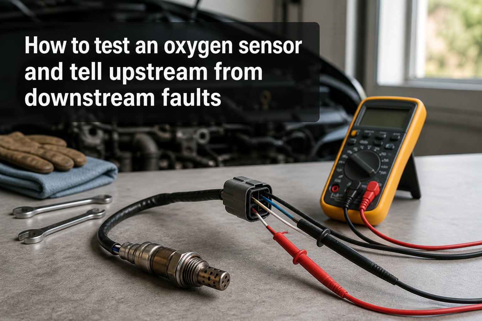
That glowing check engine light staring back at you might be your oxygen sensor crying for help. The problem is figuring out whether the upstream or downstream sensor went bad, and whether you actually need to replace it or just clean the connections. If you have been hunting through forums at midnight trying to decode a P0130 or P0141, you are in the right place.
Learning how to test an oxygen sensor is one of those skills that pays for itself the first time you use it. A single unnecessary sensor replacement at a shop can run you parts plus an hour of labor, while a multimeter test takes about 20 minutes in your driveway. You just need to know which wire to probe and what numbers to expect.
In this guide I will walk you through every method I use to test O2 sensors, from multimeter voltage checks to OBD2 scanner graphing. I will also show you exactly how to tell whether your fault is upstream or downstream, because that distinction changes everything about your diagnosis and repair. By the end you will have the confidence to pick up a meter, read those voltage swings, and know whether the sensor is the real problem or just an innocent bystander.
Table of Contents
What an Oxygen Sensor Actually Does?
An oxygen sensor measures the amount of oxygen left in your exhaust gas and reports it to your engine computer as a voltage signal. The ECU uses that signal to constantly adjust the air-fuel mixture, keeping it as close to the ideal 14.7:1 stoichiometric ratio as possible. Without a working O2 sensor, your engine runs blind and falls back on preset fuel maps that are far less efficient.
A healthy zirconia narrowband sensor generates between 0.1V and 0.9V. Low voltage around 0.1V to 0.3V means the mixture is lean, meaning too much air and not enough fuel. High voltage around 0.7V to 0.9V means the mixture is rich, meaning too much fuel and not enough air.
In normal closed-loop operation the voltage should constantly sweep back and forth across that range, crossing 0.45V roughly two to five times per second at idle. That rapid switching is what the ECU uses to fine-tune fuel trim in real time. A sensor stuck at a fixed voltage, slow to respond, or flatlined at 0V or 0.5V is telling you something is wrong.
Upstream vs Downstream: How to Tell Them Apart
The single most confusing part of O2 sensor diagnosis is knowing which sensor you are dealing with. Every modern car has at least two oxygen sensors, and some V6 and V8 engines have four. They are not interchangeable in function, and a fault in one means something completely different from a fault in the other.
Upstream Sensors (Sensor 1)
The upstream oxygen sensor sits in the exhaust before the catalytic converter, usually right where the exhaust manifold meets the downpipe. Mechanics call it Bank 1 Sensor 1 or Bank 2 Sensor 1 depending on which cylinder head it serves. This sensor is the one the ECU actually listens to for fuel trim adjustments.
Because it directly controls your air-fuel mixture, a bad upstream sensor affects how your engine runs. You will feel symptoms like rough idle, poor fuel economy, hesitation under acceleration, and sometimes a sulfur smell from the exhaust. The upstream sensor switches rapidly in normal operation, so sluggish voltage response is a classic failure sign.
Downstream Sensors (Sensor 2)
The downstream oxygen sensor sits after the catalytic converter, usually bolted into the exhaust pipe somewhere under the cabin area. Its only job is monitoring catalytic converter efficiency, not controlling fuel mixture. The ECU compares the downstream reading against the upstream reading to confirm the cat is doing its job.
A downstream sensor should read relatively flat and steady compared to the upstream sensor, typically holding near 0.5V to 0.7V if the catalytic converter is healthy. If the downstream voltage starts mirroring the upstream switching pattern, the ECU sets a catalyst efficiency code. That means either your cat is failing or the downstream sensor itself is lying.
Bank 1 vs Bank 2 Explained
Bank 1 is always the side of the engine where cylinder number one lives. On an inline four-cylinder engine there is only one bank, so you only deal with Bank 1 Sensor 1 and Bank 1 Sensor 2. On V6 and V8 engines, Bank 2 is the opposite cylinder head, giving you four sensors total: Bank 1 Sensor 1, Bank 1 Sensor 2, Bank 2 Sensor 1, and Bank 2 Sensor 2.
To identify Bank 1 on a V-engine, look for the cylinder head positioned furthest forward in the engine bay, since cylinder one is always the frontmost cylinder on that side. On transverse engines the bank numbering varies by manufacturer, so checking a factory service manual or a reliable online diagram for your specific vehicle is worth the five minutes it takes.
How to Test an Oxygen Sensor with a Multimeter?
This is the hands-on part. A digital multimeter is the most accessible tool for O2 sensor testing, and the procedure works whether you have a 1-wire, 3-wire, or 4-wire sensor. The key is getting the engine fully warm first, because a cold sensor will not produce accurate voltage no matter how good it is.
Step 1: Warm the Engine to Operating Temperature
Start the engine and let it reach full operating temperature, which usually means the coolant temperature gauge sitting at the middle of its range. Give it at least 10 minutes of driving or idling. O2 sensors need heat to function, and testing on a cold engine gives you garbage readings every time.
Step 2: Locate the Signal Wire
On a 4-wire sensor you are looking for the signal wire, which is typically the one color that differs from the heater pair and the ground. Common conventions are a black wire for signal on many Denso sensors, or a purple wire on some Bosch units, but always verify against a wiring diagram for your vehicle. On a 1-wire sensor the single wire is the signal wire, and the sensor body grounds through the exhaust itself.
Step 3: Set the Multimeter to DC Voltage
Set your digital multimeter to DC volts in a range that covers at least 1V. Back-probe the signal wire gently without piercing the insulation if you can avoid it, since piercing causes corrosion problems later. Connect the black multimeter lead to a good engine ground.
Step 4: Read the Voltage at Idle
With the engine idling in closed loop, a healthy upstream sensor should sweep rapidly between roughly 0.1V and 0.9V. You should see the numbers jumping constantly rather than holding still. If the voltage is stuck at a fixed value, switches very slowly, or never moves from 0V, the sensor is likely bad.
Step 5: Force a Rich and Lean Swing
To confirm the sensor can actually respond, create a momentary rich condition by snapping the throttle open briefly, which should push voltage above 0.8V. Then pull a small vacuum line to introduce a lean condition, which should drop voltage below 0.2V. A sensor that fails to swing between those extremes under forced conditions is confirmed faulty.
For the downstream sensor, expect a much steadier reading that holds relatively flat rather than sweeping. If the downstream sensor mimics the rapid switching of the upstream sensor, your catalytic converter is likely worn out rather than the sensor being bad.
How to Test an Oxygen Sensor with an OBD2 Scanner
A scan tool gives you live data without poking wires, and on many vehicles it is actually the faster method. You can watch exactly what the ECU sees, graph multiple sensors at once, and compare upstream against downstream in real time. Forum users on ScannerDanner frequently recommend graphing sensors rather than just reading numbers, because visual patterns reveal sluggish response that raw numbers hide.
Step 1: Connect the Scanner and Read Stored Codes
Plug your OBD2 scanner into the port under the dash, usually within reach of the driver seat. Read any stored codes first and note them, because the specific code tells you which sensor position to focus on. Clear old codes if you want a fresh start, but write them down first.
Step 2: Access Live Data for Oxygen Sensors
Navigate to live data or data stream on your scanner and select the O2 sensor or oxygen sensor B1S1 PID. Most scanners let you view multiple sensors side by side, which is exactly what you want for upstream versus downstream comparison. Look for voltage readings or, on newer vehicles with broadband sensors, current readings in milliamps.
Step 3: Graph and Compare Patterns
Start the engine, let it warm up fully, and watch the upstream sensor voltage graph. You should see a rapid switching pattern crossing the midpoint roughly two to five times per second at warm idle. If the pattern looks lazy, flat, or stuck high or low, the sensor is underperforming.
Now overlay the downstream sensor on the same graph. It should look noticeably flatter and steadier than the upstream. If the two patterns look nearly identical, the catalytic converter is not cleaning the exhaust effectively and you likely have a cat efficiency problem rather than a sensor failure.
Step 4: Check Freeze Frame Data
When the check engine light triggered, the ECU saved a freeze frame showing engine conditions at that exact moment. Pull up the freeze frame for your O2 sensor code and look at what the sensor was reading when the fault set. This often reveals whether the sensor was stuck lean, stuck rich, or slow to respond, which directly confirms the failure mode.
Testing the Heater Circuit
Modern sensors have an internal heater element that gets the sensor up to operating temperature fast, since cold sensors do not produce accurate readings. When that heater fails, you get codes like P0141, P0135, P0155, or P0161, all of which are heater circuit malfunction codes for different sensor positions. The good news is the heater is the easiest part to test.
Step 1: Identify the Heater Wires
On a 4-wire sensor, two wires handle the heater circuit and they are usually the same color or a matched pair, commonly two white wires or a white and black pair. The other two wires are the signal and signal ground. Check a wiring diagram to confirm, because guessing here wastes time.
Step 2: Test Resistance with the Sensor Disconnected
Unplug the sensor connector and set your multimeter to ohms or resistance. Probe the two heater terminals on the sensor side, not the harness side. A healthy heater element typically reads between 6 and 20 ohms depending on the sensor, with many common Denso units landing around 10 to 13 ohms.
If you read infinite resistance, also shown as OL on most meters, the heater element is open and the sensor is dead. If resistance is near zero ohms, the element is shorted. Either way the sensor needs replacing.
Step 3: Verify Harness Voltage
With the key in the ON position and the engine off, probe the two heater pins on the harness side of the connector. You should see battery voltage, around 12V, on one of the pins with the other being ground. If you have no voltage at the harness, the problem is in the wiring or the relay, not the sensor.
Oxygen Sensor DTC Code Reference (P0130 to P0169)
Diagnostic trouble codes in the P0130 to P0169 range all point at oxygen sensor circuits, and the numbering follows a predictable pattern once you understand how it works. The key is knowing that codes in the P013x range relate to Bank 1, while codes in the P015x range relate to Bank 2 on V-configuration engines.
Bank 1 Upstream Codes (Sensor 1)
P0130 indicates an oxygen sensor circuit malfunction for Bank 1 Sensor 1, meaning the ECU is not seeing a plausible signal from the upstream sensor on the number-one cylinder bank. P0131 means that sensor voltage is too low, indicating a lean condition signal that may be real or may be a dead sensor. P0132 means voltage is too high, pointing at a rich signal.
P0133 is a slow response code, meaning the sensor is switching but not fast enough to keep up with fuel trim demands. P0134 means no activity detected, which usually means the sensor is completely dead or the signal wire is broken. P0135 is the heater circuit malfunction code for Bank 1 Sensor 1.
Bank 1 Downstream Codes (Sensor 2)
P0136 through P0139 mirror the upstream codes but apply to Bank 1 Sensor 2, the downstream sensor after the catalytic converter. P0136 is a general circuit malfunction, P0137 is low voltage, P0138 is high voltage, and P0139 is slow response. P0141 is the heater circuit code for the downstream sensor, and this is one of the most common O2 codes people ask about.
Bank 2 Codes
Codes P0150 through P0159 mirror the entire Bank 1 sequence but apply to Bank 2 Sensor 1 and Bank 2 Sensor 2 on engines with two cylinder banks. P0150 is Bank 2 Sensor 1 circuit malfunction, P0153 is slow response on Bank 2 upstream, and P0155 is the Bank 2 Sensor 1 heater code. Codes P0156 through P0161 cover the Bank 2 downstream sensor, with P0161 being the heater circuit fault.
Quick Decoder
Here is a shortcut for reading any P0130-range code. The middle digit tells you the bank: zero means Bank 1, five means Bank 2. The last digit tells you the position and fault type: zero through four relate to Sensor 1 signal issues, six through nine relate to Sensor 2 signal issues, and any code ending in five or one is a heater circuit code.
Symptoms: Upstream vs Downstream Failure Comparison
One of the biggest pain points forum users describe is not knowing which sensor is causing their problem. The symptoms of upstream and downstream failures overlap in some ways but differ significantly in others, and understanding those differences narrows your diagnosis fast.
Upstream Sensor Failure Symptoms
When the upstream sensor fails, the ECU loses its primary input for fuel trim, so drivability suffers directly. You will likely notice poor fuel economy, rough idle, hesitation or stumbling under acceleration, a persistent smell of unburned fuel, and sometimes black smoke from the tailpipe. The check engine light will usually illuminate with an active code rather than a pending one.
Upstream failures can also trigger secondary codes. A dead upstream sensor that reports a constant lean condition can cause the ECU to dump fuel trying to compensate, which then ruins your catalytic converter over time. This is why ignoring an upstream sensor fault gets expensive quickly.
Downstream Sensor Failure Symptoms
Downstream sensor failures are far less dramatic because these sensors do not control fuel mixture. The most common symptom is simply a check engine light with a catalyst efficiency code like P0420 or P0430, even though the catalytic converter itself may be fine. You usually will not feel any change in how the engine runs.
A heater failure on the downstream sensor, such as a P0141, typically produces no drivability symptoms at all. The ECU just flags the circuit fault. This is why many people drive for months with a bad downstream sensor without noticing anything wrong beyond the dashboard light.
Side-by-Side Summary
If your engine runs rough, burns more fuel, or hesitates under load, suspect the upstream sensor first. If your only symptom is a check engine light with no change in how the car drives, the downstream sensor or the catalytic converter is the more likely culprit. A scan tool confirming which code is set will pinpoint it immediately.
Can You Bench Test or Unplug Test an O2 Sensor?
Forum mechanics frequently ask about two shortcut testing methods that do not require any tools: the unplug test and the bench test. Both have limited value but are worth understanding.
The Unplug Test
Some forum users suggest unplugging the upstream sensor and seeing whether the idle improves or changes. The theory is that if the sensor was feeding bad data, unplugging it forces the ECU into open-loop mode using default fuel maps, which can mask a sensor problem. In practice, unplugging the upstream sensor usually causes rougher running, not smoother, and it will definitely trigger a check engine code.
Unplugging the downstream sensor is harmless to drivability since it does not affect fuel trim. People sometimes do this to clear a false catalyst efficiency code temporarily, but it will set a new code for the disconnected sensor circuit within a few drive cycles. It is a diagnostic band-aid, not a fix.
The Bench Test
Bench testing involves removing the sensor and heating the tip with a propane torch while measuring voltage output. A functional zirconia sensor will produce a voltage when heated in the presence of a flame. This method can confirm whether the sensing element is completely dead, but it cannot reveal sluggish response or intermittent failures, which are the most common real-world problems.
I consider bench testing a last resort. Removing the sensor risks damaging the threads or the wiring harness, and you still need to reinstall and road-test afterward. The in-vehicle multimeter test gives you far more useful information with less effort.
When to Replace vs Clean an Oxygen Sensor
Not every O2 sensor problem requires replacement. Sometimes the sensor is fine and the wiring, connector, or exhaust leak upstream is the real culprit. Knowing when to clean, when to repair wiring, and when to replace saves you money and frustration.
Visual Inspection Checklist
Before ordering any parts, get under the car and look at the sensor and its wiring. Check for melted or chafed wires near the exhaust, corroded connector pins, and exhaust leaks at the manifold gasket or flex pipe ahead of the sensor. An exhaust leak upstream of the sensor pulls in outside oxygen and makes the sensor read artificially lean, which mimics a bad sensor perfectly.
Look at the sensor tip if you can see it. Heavy white or light gray deposits indicate coolant burning or silicone contamination, which usually means the sensor is ruined. Black sooty deposits may indicate a rich running condition, and the sensor might recover once you fix the underlying fuel issue. Greenish deposits suggest oil contamination from worn valve seals or piston rings.
When Cleaning Helps
O2 sensors are not really cleanable in the traditional sense. Spraying them with cleaner or soaking them in solvent rarely restores function and can damage the sensing element. If contamination from a rich condition or oil consumption coated the sensor, fixing the root cause and driving for a few hundred miles may let the sensor recover on its own as it burns off deposits.
When Replacement Is the Answer
If your multimeter test shows the sensor producing no voltage, stuck at a fixed value, or responding too slowly to throttle changes, replacement is the correct fix. Heater circuit failures with confirmed open or shorted elements also require replacement, since the heater cannot be repaired separately. Buying a quality OEM-equivalent sensor from brands like Denso or Bosch rather than the cheapest option available makes a real difference in longevity and accuracy.
For the average DIYer, a quality sensor runs between 50 and 150 dollars depending on the vehicle, and replacing it yourself with an oxygen sensor socket takes about 30 minutes per sensor. Compare that to a shop charging diagnostic time plus an hour of labor per sensor, and the savings add up fast.
FAQs
How can I tell an upstream O2 sensor from a downstream O2 sensor?
The upstream sensor sits in the exhaust before the catalytic converter, usually right at the manifold-to-pipe junction. The downstream sensor sits after the catalytic converter, further back under the vehicle near the cabin. Bank 1 Sensor 1 is upstream, and Bank 1 Sensor 2 is downstream.
How to know if an upstream O2 sensor is bad?
A bad upstream sensor typically causes poor fuel economy, rough idle, hesitation under acceleration, and a sulfur or raw fuel smell. A scan tool will show sluggish or flat voltage instead of the normal rapid switching between 0.1V and 0.9V. Codes in the P0130 to P0135 range point directly at Bank 1 Sensor 1.
Is there a way to bench test an O2 sensor?
You can remove the sensor, heat the tip with a propane torch, and measure voltage output with a multimeter. A functional zirconia sensor produces a voltage when heated. However, bench testing only confirms a completely dead sensor and cannot detect sluggish response, which is the most common real failure mode.
What happens if I unplug my downstream O2 sensor?
Unplugging the downstream sensor has no effect on engine performance or fuel trim because it does not control mixture. It will trigger a check engine light and set a circuit code within a few drive cycles. Some people unplug it temporarily to mask a false catalyst efficiency code, but this is not a permanent fix.
How to test an O2 sensor without a scanner?
Use a digital multimeter set to DC volts. Warm the engine fully, back-probe the signal wire, and connect the black lead to engine ground. A healthy upstream sensor should sweep rapidly between 0.1V and 0.9V. Snap the throttle to force a rich swing above 0.8V, then create a lean condition to confirm the sensor drops below 0.2V.
Is P0141 upstream or downstream?
P0141 is a downstream sensor code. Specifically it is a heater circuit malfunction for Bank 1 Sensor 2, the oxygen sensor located after the catalytic converter. The sensor position numbering is: Sensor 1 is upstream, Sensor 2 is downstream, and the last digit pattern ending in five or one indicates a heater circuit fault.
Can a bad O2 sensor cause a P0130 code?
Yes, P0130 means the ECU is not seeing a plausible signal from the Bank 1 upstream oxygen sensor. A completely dead sensor, a broken signal wire, or a sensor stuck at a fixed voltage will all trigger P0130. Test the signal wire with a multimeter to confirm whether the sensor itself is faulty or the wiring is the issue.
How to tell if an O2 sensor is bad with voltage readings?
A good upstream sensor sweeps rapidly between 0.1V and 0.9V several times per second. A sensor stuck at 0V, flatlined at a fixed voltage, slow to respond to throttle changes, or never reaching above 0.8V under rich conditions is likely bad. The downstream sensor should read relatively steady near 0.5V to 0.7V if the catalytic converter is healthy.
Conclusion
Testing an oxygen sensor comes down to two reliable methods: a multimeter on the signal wire or an OBD2 scanner watching live data. Either way, a healthy upstream sensor sweeps between 0.1V and 0.9V several times per second, and a healthy downstream sensor holds relatively steady after the catalytic converter. Knowing that distinction is what lets you tell upstream from downstream faults with confidence.
The code numbering does the rest of the work for you. Codes in the P0130 to P0135 range mean Bank 1 upstream, P0136 to P0141 mean Bank 1 downstream, and the P0150s mirror everything for Bank 2. Before you order a replacement sensor, always verify with a voltage test or scan tool graph, because exhaust leaks, wiring damage, and contaminated sensor tips can mimic a dead sensor and waste your money.
Grab your multimeter, warm up the engine, and start with the signal wire. Once you see those voltage numbers dancing on the meter, you will know within minutes whether the sensor deserves a replacement or the problem lives somewhere else in the exhaust.