
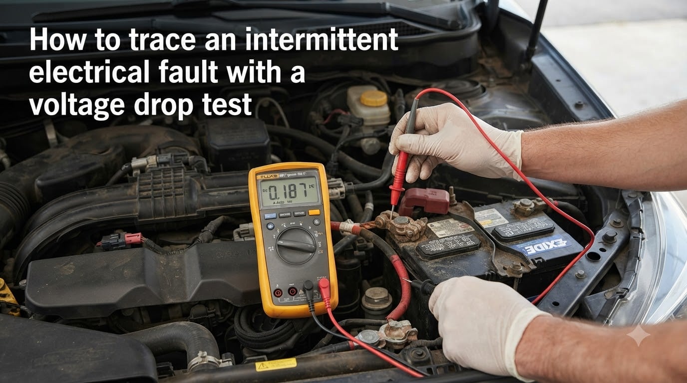
Intermittent electrical faults are the most frustrating problems you can face, whether you are working on a vehicle, a home circuit, or industrial equipment. The component works fine one minute and fails the next, leaving you guessing. The good news is that a voltage drop test can find these elusive faults, even when they refuse to show up during a standard inspection.
I have spent years tracing electrical gremlins that other diagnostic methods missed entirely. The voltage drop test remains the single most reliable technique in my toolkit for finding bad connections, corroded terminals, and damaged wires that only fail under load. Learning how to trace an intermittent electrical fault with a voltage drop test will save you hours of frustration and prevent unnecessary parts replacement.
In this guide, we will walk through the entire process step by step. You will learn why standard voltage checks miss intermittent faults, how to set up and perform a voltage drop test correctly, what readings tell you about circuit health, and advanced techniques for catching faults that only appear under specific conditions.
Whether you are a DIYer chasing a mysterious electrical issue in your car or a homeowner tracking down a flickering circuit, this method will change how you approach fault diagnosis.
Table of Contents
What Is a Voltage Drop Test and Why It Works for Intermittent Faults?
A voltage drop test measures the voltage lost across a connection, wire, or component while current is actively flowing through the circuit. When everything is clean and tight, the voltage drop is nearly zero. When corrosion, loose connections, or damaged wires introduce unwanted resistance, voltage drops across that resistance and your meter reads it directly.
This test works so well for intermittent faults because it catches problems that only appear when the circuit is working. A corroded connector might pass a visual inspection and even show full battery voltage when tested with no load. But the moment current flows through it, the resistance causes a measurable voltage drop that points right to the problem.
Voltage Drop vs Static Voltage: The Key Difference
Most people test circuits by checking voltage at a point, like measuring 12.6 volts at a battery terminal or at a component connector. That is static voltage, and it only tells you what voltage is available. It does not tell you whether that voltage can actually reach the load under working conditions.
A voltage drop test is fundamentally different. Instead of measuring voltage at a single point, you measure the difference in voltage between two points in the same circuit while current is flowing. If there is 0.5 volts of drop between the battery positive and the component positive terminal, you know exactly where the problem lives.
Think of it like water pressure. Checking static voltage is like measuring pressure at a faucet that is turned off. A voltage drop test is like measuring how much pressure disappears between the main supply and that faucet while water is running. A partial blockage only shows up under flow, and electrical resistance only shows up under load.
Why the Circuit Must Be Loaded
This is the single most important rule of voltage drop testing, and it is the step most DIYers skip. The circuit must be operational and under load for a voltage drop test to work. Without current flowing, there is no voltage to drop, and your meter will read zero regardless of how bad the connection is.
I have seen mechanics replace perfectly good components because they tested unloaded circuits and found normal voltage. The fault only appeared when the component drew real current through a corroded connector. Always make sure the circuit is powered and the load is active before taking any readings.
Why Intermittent Electrical Faults Are So Hard to Find
Intermittent faults earn their reputation as the hardest problems to diagnose. A completely failed component is straightforward to find because the symptoms are constant and reproducible. An intermittent fault disappears the moment you start looking for it.
Heat expansion, vibration, moisture, and changing current draw all affect whether a bad connection will fail at any given moment. A connector might work perfectly at room temperature and fail only after the engine bay heats up. A ground connection might be fine on smooth roads and fail on the first pothole you hit.
Forum discussions among mechanics and electricians consistently highlight the same frustration. The fault does not appear when the vehicle or equipment is in the shop. You drive it, use it, or power it up under real conditions, and suddenly the problem returns. This is exactly why voltage drop testing under load is so valuable. It lets you catch the fault while the circuit is actually working, even if the fault is subtle.
The key insight is that resistance from a bad connection is often marginal. It is just barely high enough to cause problems under specific conditions. Static testing will never reveal it because the resistance only becomes significant when current pushes through it. Voltage drop testing exposes that resistance directly and measurably.
How to Trace an Intermittent Electrical Fault with a Voltage Drop Test?
This step-by-step process works for automotive circuits, home wiring, and virtually any DC electrical system. The principles are the same regardless of what you are diagnosing. Follow each step in order, and document your readings as you go.
Step 1: Gather Your Tools and Set Up Safely
You need a digital multimeter capable of reading DC voltage to at least two decimal places, your test leads, and ideally a set of back-probe pins or piercing probes for accessing wires without disconnecting connectors. A wiring diagram for the specific circuit you are testing is extremely helpful for knowing where connections and splices are located.
Set your multimeter to DC volts. For most automotive work, the 20-volt range is appropriate. For home or industrial circuits, use the appropriate higher range. Always work safely around electrical systems. Disconnect battery power before accessing any wiring behind panels, and never pierce insulation on wires that will be exposed to moisture without sealing the puncture afterward.
Step 2: Put the Circuit Under Load
This step cannot be skipped. Turn on the circuit you are diagnosing so the component is actively drawing current. If you are testing a headlight circuit, turn on the headlights. If you are testing a fuel pump circuit, the pump should be running. If you are testing a home outlet, plug in a load like a lamp or heater.
For intermittent faults specifically, try to reproduce the conditions that trigger the failure. If the problem appears after the engine warms up, test it warm. If it happens during vibration, tap and wiggle connectors while monitoring the voltage drop. Reproducing the fault condition is often the difference between finding the problem and going home empty-handed.
Step 3: Test the Power Side
Place your red multimeter lead on the battery positive terminal or the power source for the circuit. Place your black lead on the positive terminal at the load component, which is the input side of whatever you are powering, such as the positive wire at the headlight bulb or the power input at a motor.
With the circuit under load, read the voltage on your meter. This reading is the voltage being lost on the power side of the circuit between the source and the load. On a healthy circuit, this reading should be very low, typically under 0.2 volts for most automotive applications. A reading of 0.5 volts or more indicates unwanted resistance somewhere in the power feed.
Move your black lead progressively closer to the power source, testing at each connection, splice, or switch along the way. When the voltage drop suddenly decreases between two test points, the fault is located between those two points. This is the back-probe method that narrows down the exact location of the problem.
Step 4: Test the Ground Side
Move your red lead to the negative or ground terminal at the load component. Place your black lead on the battery negative terminal or the main ground point for the circuit. The circuit must still be under load for this test to work.
Read the voltage drop on the ground side. A healthy ground path should show very low voltage drop, under 0.2 volts for most automotive circuits and near zero for home wiring grounds. Excessive ground-side voltage drop is one of the most common causes of intermittent electrical problems, yet it is frequently overlooked because people focus only on the power side.
Bad grounds cause all sorts of phantom symptoms. Dim lights, slow motors, erratic sensor readings, and intermittent failures often trace back to a loose or corroded ground connection that tests fine visually but fails under load. The voltage drop test catches these every time.
Step 5: Narrow Down the Fault Location
Once you have identified which side of the circuit has excessive voltage drop, systematically move your test leads to isolate the exact location. Test across each connection, switch, relay contact, and wire segment. The voltage drop will be highest across the component or connection that is causing the problem.
This is where patience pays off. An intermittent fault might require several rounds of testing under different conditions before it reveals itself. Keep the circuit loaded, reproduce the fault conditions as closely as possible, and let your meter guide you to the resistance.
Understanding Voltage Drop: Acceptable vs Problematic Readings
Knowing what constitutes a normal reading versus a problem reading is essential for effective diagnosis. The numbers differ slightly depending on the circuit type, voltage level, and application, but the general guidelines below cover the most common scenarios.
Rule of Thumb for Voltage Drop Limits
For 12-volt automotive circuits, a commonly accepted rule of thumb is that total circuit voltage drop, combining both power and ground sides, should not exceed 0.5 volts. Individual connections should show less than 0.1 volts of drop. Starter motor circuits allow slightly more, up to 0.5 volts on each side, because they draw very high current.
For 120-volt home circuits, voltage drop should not exceed 3% of the supply voltage, which is about 3.6 volts. For sensitive electronic circuits and low-voltage signal wiring, even 0.05 volts of drop across a single connection can cause problems. When in doubt, compare your reading to a known-good identical circuit if one is available.
The most reliable approach is to compare readings from both sides of the circuit. If the power side shows 0.8 volts of drop and the ground side shows 0.1 volts, the problem is on the power side. If the power side is clean at 0.05 volts but the ground side reads 0.7 volts, focus your attention on the ground path.
Power Side vs Ground Side Voltage Drop Testing
Testing the power side and ground side requires different lead placements but follows the same principle. You are always measuring the voltage difference between two points in the circuit while current flows through it.
For power side testing, you measure from the positive source to the positive input at the load. This checks every wire, fuse, switch, relay, and connector that carries current to the component. High readings here point to problems in the feed path, such as a corroded fuse terminal, a worn relay contact, or oxidized wire.
For ground side testing, you measure from the negative output at the load back to the battery negative or main ground. This checks the return path that current takes to complete the circuit. Ground side problems are incredibly common and notoriously difficult to find without voltage drop testing because bad grounds often look fine visually.
Always test both sides. Diagnosing only the power side misses half the circuit, and ground faults are just as likely as power faults to cause intermittent problems. A complete diagnosis measures both sides and calculates total circuit voltage drop to confirm where the resistance lives.
Common Locations Where Voltage Drop Faults Hide
Certain locations in any electrical system are more prone to developing excessive resistance. Knowing where to look first can save significant diagnostic time. Based on real-world troubleshooting experience, these are the most frequent culprits.
Connector terminals top the list, especially those exposed to heat and moisture. Push-together connectors develop corrosion between the terminals over time. The connection looks secure from the outside, but the contact surfaces oxidize and create resistance that only shows up under load.
Ground connections are the next most common source of voltage drop faults. Ground bolts loosen from vibration, paint or undercoating insulates the connection, and the metal-to-metal contact area corrodes. In vehicles, chassis ground points near wheel wells and engine mounts are particularly vulnerable.
Switch and relay contacts wear over time. Every time a switch opens and closes, a tiny arc occurs that erodes the contact surface. After thousands of cycles, the contacts develop pitting and oxidation that creates resistance. Relay contacts fail the same way, and high-current relays like fuel pump and starter relays are especially prone to this wear pattern.
Fuse and fuse box terminals accumulate corrosion, particularly in environments with temperature cycling and humidity. The fuse may test good for continuity, but the terminals it plugs into can develop enough resistance to cause a voltage drop. Battery terminals and cable ends round out the list, as lead oxidation and acid corrosion build up gradually.
Advanced Tips for Capturing Intermittent Faults
Some intermittent faults refuse to appear during a standard test session. These advanced techniques help reproduce the conditions that trigger failures and capture data that a one-time multimeter reading might miss.
The wiggle test is one of the simplest and most effective methods for intermittent faults. With the circuit under load and your meter connected across a suspect connection, physically wiggle, tap, and flex the wiring harness. If the voltage drop reading spikes when you move a particular area, you have found a loose connection or broken wire inside the insulation.
Thermal imaging is an increasingly accessible tool that complements voltage drop testing beautifully. Resistance generates heat, and a thermal camera can spot connections that are running hot before they fail completely. Scan the circuit under load and look for connectors or components that are warmer than their neighbors. A connection showing even a few degrees above ambient under load is a prime suspect for intermittent failure.
Data logging takes fault capture to the next level. Some digital multimeters and most oscilloscopes can record voltage readings over time. Set up the logger to monitor voltage at the load component during normal operation, then review the data after the fault occurs. A momentary voltage dip captured in the log confirms that the problem is real and shows exactly when it happens.
Heat guns and freeze spray are useful for temperature-sensitive faults. If a connector only fails when hot, warm it gently with a heat gun while monitoring voltage drop. If the problem appears only when cold, use freeze spray on individual components. This binary approach isolates which connection is thermally sensitive.
For automotive work, consider driving with a passenger monitoring the meter, or use a recording multimeter mounted where the driver can see it. Real-world conditions produce real faults, and sometimes the only way to catch an intermittent problem is to test it during actual use.
Common Multimeter Mistakes to Avoid
Even experienced technicians make errors that compromise voltage drop test results. Avoiding these common mistakes ensures your readings are accurate and your diagnosis is reliable.
The most frequent mistake is testing without load. We covered this already, but it bears repeating because it accounts for more failed diagnoses than any other error. If the circuit is not powered and the component is not operating, your voltage drop reading is meaningless. Always confirm the load is active before trusting any measurement.
Using the wrong meter range is another common problem. If your meter is set to a range that is too high, you lose resolution and small but significant voltage drops may not register. Use the lowest range that accommodates the expected reading. For most automotive voltage drop tests, the 2-volt or 200-millivolt range provides the resolution you need.
Poor probe contact produces false readings. Make sure your test leads are making solid metal-to-metal contact with the test points. Alligator clips or back-probe pins provide more reliable connections than holding probes by hand. A loose probe contact can add its own resistance and create phantom voltage drop readings that send you chasing non-existent problems.
Finally, do not ignore the meter leads themselves. Damaged or low-quality test leads can introduce resistance that affects your readings. If you suspect your leads, touch the probes together while in resistance mode. A good set of leads should read very close to zero ohms. Replace leads that show significant resistance.
FAQs
How to diagnose a voltage drop?
To diagnose a voltage drop, set your multimeter to DC volts, place the test leads across the connection or wire segment you want to check, and make sure the circuit is under load. Any reading above 0.1 volts on a single automotive connection or above 0.5 volts total for the circuit indicates excessive resistance that needs attention.
How do you trace an electrical fault?
Trace an electrical fault by putting the circuit under load, then using voltage drop testing to measure across each connection, switch, and wire segment from the power source to the load and back through the ground path. Move your test leads progressively along the circuit. The point where voltage drop is highest is where the fault is located.
What is the rule of thumb for voltage drop?
The general rule of thumb is that total voltage drop across a complete 12-volt circuit should not exceed 0.5 volts. Individual connections should show less than 0.1 volts of drop. For 120-volt home circuits, voltage drop should stay under 3% of supply voltage, approximately 3.6 volts.
How to interpret the results of a voltage drop test?
Interpret voltage drop results by comparing readings to known good values. Under 0.1 volts on a single automotive connection is healthy. Between 0.1 and 0.3 volts suggests minor resistance worth monitoring. Above 0.3 volts on a connection or 0.5 volts total for the circuit indicates a problem that needs repair. Always test both power and ground sides to identify which side has the fault.
Why does my circuit show voltage drop only when load is applied?
Voltage drop only appears under load because resistance only causes a measurable voltage loss when current is flowing through it. A corroded or loose connection may pass full voltage when tested with no current draw, but the moment the component turns on and current flows, the resistance creates a voltage drop. This is why standard voltage checks miss intermittent faults that voltage drop testing catches.
What causes intermittent electrical faults in vehicles?
Intermittent electrical faults in vehicles are caused by loose connectors, corroded terminals, damaged wiring, worn switch and relay contacts, bad ground connections, and heat-sensitive components. These problems only manifest under specific conditions like temperature changes, vibration, or moisture, which is why they are difficult to reproduce during testing.
Putting It All Together
Tracing an intermittent electrical fault with a voltage drop test is a skill that pays dividends every time you use it. The core principles are simple: the circuit must be loaded, you measure voltage difference between two points under load, and high readings point directly to resistance in the circuit.
Remember to always test both the power and ground sides, use the lowest appropriate meter range for best resolution, and reproduce the conditions that trigger the fault. Advanced tools like thermal cameras and data loggers can help with stubborn problems, but a basic multimeter and the techniques in this guide will solve the vast majority of intermittent electrical issues you encounter.
The next time a component works intermittently and you are tempted to start replacing parts, grab your multimeter and run a voltage drop test first. It takes minutes, costs nothing, and points you directly to the problem. That is the difference between guessing and knowing when it comes to electrical diagnosis.