
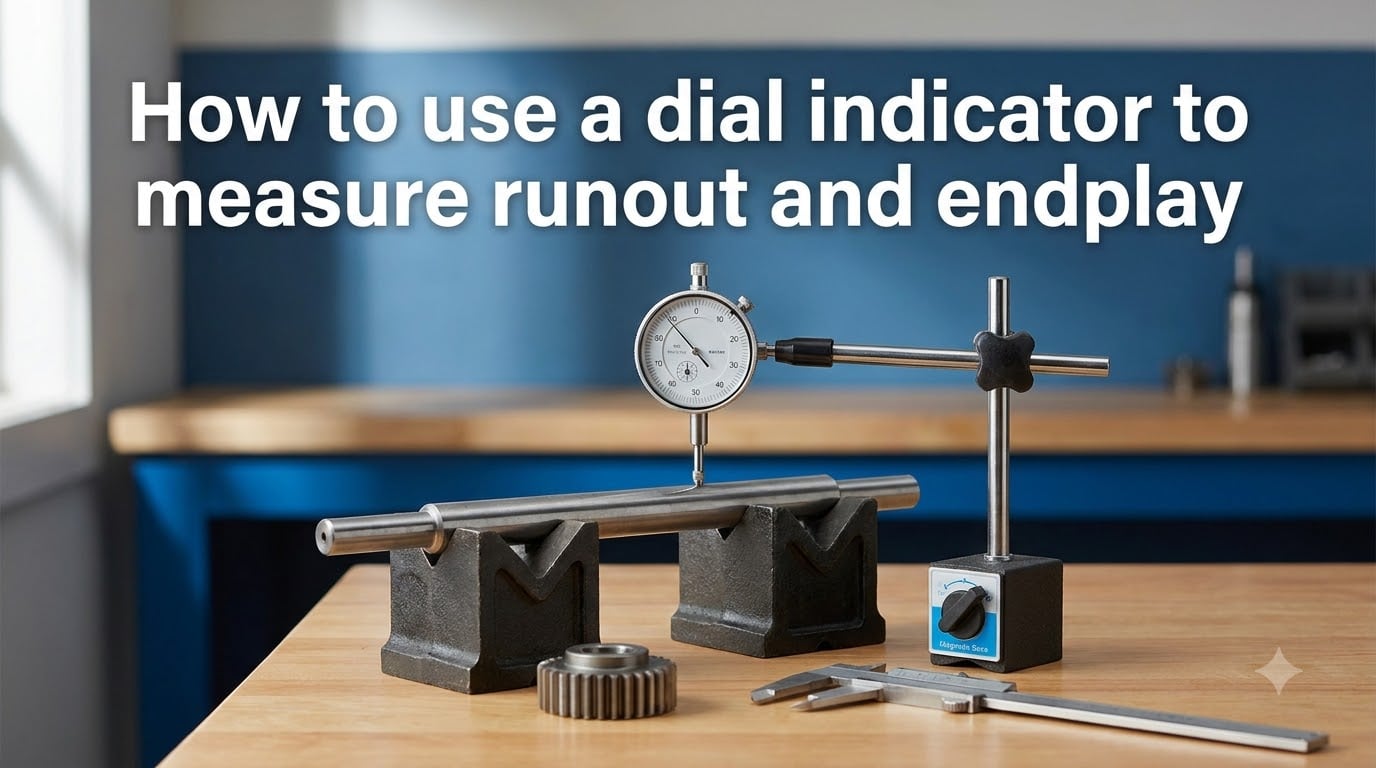
Learning how to use a dial indicator to measure runout and endplay is one of the most practical skills a mechanic, machinist, or serious DIYer can pick up. I picked it up working in my own garage on brake rotors and trailer wheel bearings, and it changed how I diagnose vibration and bearing wear. This guide walks you through the same process I use: what the tool is, how the parts work, how to set it up, and how to get clean, repeatable readings.
A dial indicator amplifies tiny movements of a plunger into a readable needle sweep, so you can detect deviations as small as 0.0001 inch. That level of precision matters whether you’re checking a brake rotor for lateral runout, measuring wheel bearing endplay, or verifying shaft alignment on a lathe. I’ll show you the exact steps, the small habits that make readings trustworthy, and the mistakes that trip up most beginners.
Table of Contents
What is a dial indicator used for?
A dial indicator is a precision measuring instrument used to measure small distances and angles, and to amplify them for easier reading. It consists of a plunger that moves in and out, with the movement displayed on a dial face.
Mechanics, machinists, and quality inspectors reach for a dial indicator when they need to know exactly how much something is moving, wobbling, or shifting. Typical jobs include checking wheel bearing endplay on a hub, measuring brake rotor runout to diagnose steering wheel vibration, verifying shaft straightness, and centering a workpiece in a four-jaw chuck. In each case, the tool answers one question: how far does this surface move from where I started?
The reason the tool is so widely used is resolution. A standard 0.001 inch indicator resolves movement to one thousandth of an inch per graduation, and finer models go to 0.0005 inch or 0.0001 inch. That gives you a real number, not a guess, when something is out of spec.
Dial indicator vs dial test indicator: which one do you need?
A dial indicator has a straight plunger that pushes in along its axis, while a dial test indicator (also called a lever indicator) uses a pivoting lever with a small contact tip. The geometry of what you’re measuring usually decides which tool you need.
Use a standard dial indicator when the contact point can land perpendicular to a rotating shaft or a flat face. It is the right choice for measuring wheel bearing endplay on a spindle, brake rotor lateral runout, and crankshaft runout on a lathe.
Use a dial test indicator when you need to measure runout on a surface that is hard to reach head-on, like the inside of a cylinder, the side of a shaft, or a part already bolted in place. The lever swings a few millimeters side to side and the body stays out of the way. Many machinists reach for a test indicator for centering work because the contact tip sweeps across the surface as the part turns.
For most home garage jobs, a standard dial indicator on a magnetic base will cover 80 percent of what you need. If you do a lot of centering or runout on assembled parts, add a dial test indicator to the drawer.
Dial indicator parts and key terminology
Before you mount the tool, take a minute to learn the parts. The names come up in every manual and forum thread, and it saves confusion later.
- Plunger: The spring-loaded shaft that pushes against your workpiece. It moves in and out by a small distance.
- Contact point: The replaceable tip screwed to the plunger. Comes in flat, spherical, and needle shapes.
- Bezel: The outer ring of the dial. It rotates so you can align the zero mark anywhere on the face.
- Pointer: The main needle that indicates how far the plunger has moved.
- Revolution counter: A small secondary dial that counts full revolutions of the main pointer. Useful on indicators with more than 0.100 inch of travel.
- Lug or lug back: The mounting lug at the top or back of the body, used with a magnetic base or clamp.
A few specifications show up on every indicator, and they’re worth understanding.
Range is the total travel of the plunger, often 0.030 inch, 0.100 inch, 0.200 inch, or 1 inch for long-range models. Graduation is the smallest marked division on the dial, usually 0.001 inch or 0.0005 inch. Resolution is the smallest movement the indicator can display, which is normally the same as the graduation. Accuracy describes how close the reading is to the true value across the full range, and is usually a few graduation marks at worst.
When someone says they have a “.0005 dial indicator,” they mean the smallest graduation is 0.0005 inch. That level of graduation is common on indicators with 0.030 inch of travel, where the small range pairs well with the fine reading.
Runout vs endplay: what’s the difference?
Runout and endplay describe two different kinds of motion, and the indicator reads both with the same tool. The trick is how you mount it and which direction the surface moves.
Runout measures how much a surface deviates from a true circle as a part rotates one full turn. You mount the indicator so its plunger rides perpendicular to the surface, then rotate the part by hand. The total indicator reading (TIR) is the difference between the highest and lowest pointer positions during one full revolution. Runout tells you whether a shaft is bent, a brake rotor is warped, or a wheel is true.
Endplay measures how far a shaft or hub can move along its axis, the direction parallel to the rotation. You mount the indicator so its plunger pushes against the end of the shaft or the face of the hub, then push and pull the assembly in and out along its axis. The reading is the difference between the two extremes. Endplay tells you whether a bearing is adjusted correctly or is worn out.
Same tool, different setup. Mount perpendicular for runout, mount parallel to the axis for endplay.
Tools and equipment you’ll need
You can measure runout and endplay with a small kit. Here’s what I keep on my bench.
- Dial indicator with the right range for your job. For most automotive work, 0.001 inch graduation and 0.030 to 0.100 inch travel is plenty.
- Magnetic base with fine adjustment. A two-knob base that lets you swing and pivot is much easier to position than a single-knob model.
- Indicator clamp or post, if you’re working on a non-magnetic surface like aluminum.
- Clean shop rags and brake cleaner. Any grease, oil, or grit on the contact point or the measured surface will ruin a reading.
- Surface plate or known flat reference, when checking flatness or tramming a mill.
- Notebook or phone to write down numbers. You will not remember them after the third wheel.
A quick note on budget: a usable indicator and magnetic base can be had for under $80 total if you shop carefully. Spend more if you need guaranteed accuracy to 0.0005 inch or finer, but a good 0.001 inch indicator from a known brand is plenty for brake rotors, wheel bearings, and shaft runout.
How to mount and zero a dial indicator
Mounting and zeroing correctly is half the battle. Get this step right and the rest of the procedure becomes straightforward.
Step 1: Clean everything. Wipe the contact point, the magnetic base feet, and the surface you’re mounting to. A single fingerprint throws off a 0.001 inch reading.
Step 2: Mount the magnetic base. Stick the base to a clean, flat, ferromagnetic surface near the part you’ll measure. Make sure it has enough swing room to reach the contact point without straining.
Step 3: Clamp the indicator. Slide the indicator lug into the clamp on the top of the base stem. Tighten the clamp enough that the indicator body won’t drift, but not so tight that you’ll crack the lug.
Step 4: Position the contact point. Bring the contact point to the surface you’ll measure. For runout, the plunger should be perpendicular to the surface. For endplay, the plunger should press straight against the end face or shoulder of the shaft.
Step 5: Pre-load the plunger. Push the indicator forward so the plunger compresses about 0.040 to 0.080 inch. This gives you room on both sides of zero for movement in either direction.
Step 6: Rotate the bezel to zero. With the plunger pre-loaded on the surface, hold the bezel still and rotate the dial face until the pointer reads zero. If you have a revolution counter, watch it stay near a whole number too.
If the reading drifts in the first few seconds, the part is settling, the bearings are seating, or your contact is on a dirty surface. Take the reading again after a quick wiggle to settle everything.
How to measure runout with a dial indicator
Runout is the most common measurement you’ll make with a dial indicator, and the procedure is the same whether you’re checking a brake rotor, a wheel rim, or a shaft. Follow these steps and you’ll get a trustworthy total indicator reading (TIR) on the first try.
Step 1: Mount the indicator perpendicular to the surface. The plunger should ride straight onto the part, with no side load. For a brake rotor, that means on the face of the rotor about half an inch in from the outer edge.
Step 2: Zero the dial at a reference point. Pick any point on the rotation as your reference. Rotate the bezel until the pointer sits on zero. Many techs prefer to zero at the lowest reading so the highest point is easy to read as a positive number.
Step 3: Rotate the part one full turn by hand. Spin the shaft, hub, or rotor slowly through 360 degrees. Watch the pointer, not the dial face. Note the highest and lowest values the pointer reaches.
Step 4: Read TIR. TIR is the difference between the highest and lowest readings during one full revolution. If the pointer swept from +0.003 to -0.002, your runout is 0.005 inch TIR.
Step 5: Repeat at a second location. For shafts, move the indicator along the length of the part and measure again. A bent shaft will show more runout at the middle than at the ends. For brake rotors, measure near the outer edge and near the hub to spot lateral runout versus hub-to-disc assembly issues.
Step 6: Compare to spec. Most passenger car brake rotor lateral runout specs fall between 0.002 and 0.005 inch TIR. Wheel rim runout for rim brake wheels should stay under about 0.020 inch. Crankshaft journals should run under 0.001 to 0.002 inch depending on the engine. If your reading exceeds spec, you have a real problem to chase.
A small tip from my own brake jobs: I always rotate the rotor a second time after zeroing. The first pass often shows runout that settles down a bit on the second pass as everything seats. Use the second number if the difference is small.
How to measure endplay with a dial indicator
Endplay measures axial movement, so your setup looks a little different. The plunger presses straight in along the axis of the shaft, and you push the assembly in and out by hand to read the total travel.
Step 1: Mount the indicator on the spindle end. Using your magnetic base, mount the dial indicator so the contact point presses against the end of the shaft or the inboard face of the hub. The plunger should be parallel to the shaft axis, not perpendicular.
Step 2: Make sure the hub face is clean. Wipe off any gasket material, rust, or grease. A 0.005 inch film of oil can fake a real endplay reading.
Step 3: Pre-load and zero the indicator. Push the indicator forward so the plunger has about 0.040 to 0.080 inch of compression, then rotate the dial face to zero.
Step 4: Push the hub inboard while oscillating the hub. With equal hand pressure on both sides of the hub, push the hub straight inboard as far as it will go. At the same time, gently oscillate or rock the hub back and forth through a small arc to seat the bearing rollers. This step matters. Without oscillating, you’ll read too little endplay because the rollers haven’t seated.
Step 5: Set the dial to zero again. With the hub still held inboard, rotate the bezel back to zero.
Step 6: Pull the hub outboard and read. Now pull the hub straight outboard as far as it will go, oscillating as you did before. The pointer now shows the total endplay directly. No math needed.
For most trailer and light truck wheel bearings, acceptable endplay runs between 0.001 and 0.005 inch. Loose enough that the bearing isn’t preloaded, tight enough that the roller doesn’t skid under load. TMC (Technology and Maintenance Council) procedures, which most heavy-duty fleets follow, set the range similarly. Always check the manufacturer’s spec for your specific bearing.
Common applications: wheel bearings, brake rotors, and crankshafts
Here are the three jobs I get asked about most often, with the specific things to watch for on each one.
Wheel bearing endplay. Use the procedure above. The trick is even hand pressure and steady oscillation. Most late-model sealed hub assemblies are preadjusted at the factory, but on adjustable setups the spindle nut torque and endplay go hand in hand. After adjusting, re-measure to confirm you’re in spec.
Brake rotor runout. Mount the indicator on a rigid stand or magnetic base attached to a non-rotating part like the caliper adapter or steering knuckle. Measure about half an inch in from the outer edge of the rotor. Push and pull on the rotor by hand to seat it on the hub, then rotate one full turn. If runout is high but the rotor is new, suspect hub runout. If hub runout is low but rotor runout is high, suspect a warped rotor. You can’t separate the two without measuring the hub face separately.
Crankshaft runout. Support the crankshaft between centers on a lathe or in the engine block. Mount the indicator on a toolpost or magnetic base against the journal you’ll check. Rotate the crank one full turn by hand. Specs vary by engine, but most OEM limits are 0.001 to 0.002 inch TIR for main and rod journals. Higher than that means the crank needs inspection or regrinding.
How to read and interpret dial indicator measurements
Reading the dial is easy once you’ve done it a few times. The dial face is marked in graduations, usually 0.001 inch each, around the full 360 degrees. One full turn of the pointer covers 0.100 inch on most indicators, and the small revolution counter ticks up by one each time the pointer passes zero.
Add the revolution counter value (in 0.100 inch steps) to the main pointer value to get the absolute plunger position. For relative measurements like TIR or endplay, you only care about the difference between the highest and lowest readings, so the revolution counter doesn’t matter as long as the plunger doesn’t bottom out or come out of the body.
When the reading won’t settle, walk through three checks. First, is the contact point clean and on a clean surface? Second, is the magnetic base firmly attached and the indicator clamped tight? Third, are you pressing straight in on the plunger? Side load on a standard dial indicator causes stick-slip and gives false readings. A dial test indicator handles side load much better, which is one reason machinists reach for it for tramming and centering work.
Troubleshooting common dial indicator measurement errors
Even with a good setup, you’ll hit readings that don’t make sense. Here are the four problems I see most often, and what to do about each one.
Inconsistent readings. Usually caused by dirt on the contact point or the measured surface, a loose magnetic base, or a bent plunger from a previous drop. Clean everything, remount, and try again. If readings still drift, the part itself may be moving (loose bearing, cracked hub).
Pointer sticks or jumps. Side load on the plunger is the most common cause. Reposition the indicator so the contact is straight in. Internal damage from a drop can also cause stick-slip, in which case the indicator needs repair or replacement.
Reading changes as you rotate. This is normal during a runout measurement and is what you’re trying to capture. Just make sure you rotate the part, not the indicator, and watch for one full revolution.
Zero drifts between measurements. The bezel slipped, or the magnetic base shifted. Re-zero at the same reference point before each new measurement.
If the indicator has been dropped, return it to zero against a known reference (a gage block, for example) and check at several points across the range. A damaged indicator will read correctly at zero and increasingly wrong as the plunger moves through its travel. That kind of damage usually means the indicator is done.
Frequently Asked Questions
Can a dial indicator measure runout?
Yes. Mount the indicator so its plunger rides perpendicular to a rotating surface, zero the dial, rotate the part one full turn by hand, and read the difference between the highest and lowest pointer positions. That reading is the total indicator runout, or TIR.
How to properly use a dial indicator?
Clean the contact point and the surface you’re measuring, mount the indicator on a magnetic base so the plunger rides straight onto the part with no side load, pre-load the plunger by about 0.040 to 0.080 inch, rotate the bezel to zero, then take your reading. Always rotate the workpiece, not the indicator, when measuring runout.
What does a .0005 dial indicator mean?
It means the smallest graduation marked on the dial is 0.0005 inch. Each tick of the pointer equals half a thousandth of an inch. Indicators with 0.0005 inch graduations usually have a shorter total range, often 0.030 inch, so the fine reading pairs with a small travel.
How to use a dial indicator to measure flatness?
Set the part on a known flat surface plate, mount the indicator so its plunger rests on the part surface, zero the dial, then sweep the indicator slowly across the part in a grid pattern. The highest and lowest readings give you the flatness variation. For best results, repeat with the part flipped 180 degrees to average out any setup error.
Final thoughts
Learning how to use a dial indicator to measure runout and endplay is mostly about building good habits. Clean surfaces, perpendicular plunger contact, pre-load on the plunger, and a stable magnetic base will give you trustworthy numbers every time. The actual reading takes seconds once the setup is right.
Practice on something you can verify, like a brake rotor you know is good, before you trust the tool on a job that matters. Compare your readings to the manufacturer’s spec, write them down, and re-zero between each measurement. With those habits in place, a $70 indicator and magnetic base will handle most of the precision measurement work in your garage.
1 thought on “How to Use a Dial Indicator (September 2026)?”